The Ossila office will be closed on December 27th, December 28th, and January 3rd. Quotes and orders will be processed on the next working day.
Glovebox Leaks, Box Design, Applications and More
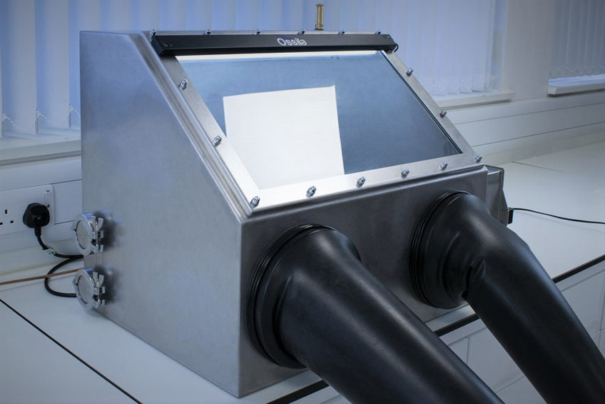
The Ossila Glove Box
Laboratory glove boxes (or gloveboxes) are used to either protect sensitive materials from the outside environment (isolation) or to protect the user from infectious samples or radioactive materials (containment). Glove boxes create a stable, sealed environment for work that involves hazardous materials, chemicals, or samples that react readily with air. A clear panel allows the contents to be seen, while the gloves themselves allow them to be manipulated. Smaller, secondary chambers called antechambers allow items to be added or removed without exposing the inside of the glovebox to the atmospheric conditions.
Inert atmosphere isolation glove boxes are the most commonly used type of glove box. The main chamber of such a glove box is generally filled with an inert gas, usually Argon or Nitrogen, to create an environment that is completely isolated from the atmosphere outside the glovebox.
Once all the air in the system has been displaced with the inert gas, the chamber of an inert atmosphere isolation glove box is sealed and maintained at an overpressure to ensure that no gasses leak into the system. By comparison, containment glove boxes operate at an under pressure to ensure that nothing escapes from the system into the outside environment.
Gloveboxes are one of the most critical pieces of equipment that can be found in any laboratory. They provide researchers with the means to work in an environment that is completely inert, eliminating the presence of reactive species such as oxygen and water. This is crucial for applications where the presence of small quantities of these elements can result in significant chemical or physical changes in the properties of the materials being used. Common uses for inert atmosphere glove boxes include chemical synthesis, organic electronics, additive manufacturing, materials handling and storage, development of battery technology, and perovskite electronics.
Contents
Applications that Require Glove Boxes
Chemical Synthesis
Additive Manufacturing
Materials Handling and Storage
Organic Electronics
Battery Technology
Perovskite Electronics
Sources of Contamination
Leaks in the Glove Box
Outgassing from Contents
Ingress Through Barrier Materials
Leak Detection and Testing
Causes of Glove Box Leaks
What to Do if You Suspect a Leak
Glove Box Leak Tests
Common Sources of Leaks
Glove Box Design
Stationary and Permanent Seals
Types of Gasket for Non-Permanent Seals
Permeability and Impact of Barrier Materials
Glovebox Comparison: Perovskite Case Study
References and Further Reading
Low Price Glove Box
High Accuracy Sensors
Monitoring Software
Automated Purging
Available Now £7000.00
Applications that Require Glove Boxes
Skip to: chemical synthesis, additive manufacturing, materials handling and storage, organic electronics, battery technology, perovskite electronics
An inert atmosphere glove box is an enclosed environment that is filled with an inert gas, such as nitrogen or argon. This atmosphere is then maintained by keeping an overpressure of the inert gas in the system, making glove boxes a relatively straight-forward and affordable way to create an atmosphere void of H2O and O2.
Working in such an environment is an encouraged practice for some experiments, such as when doing so may improve the quality of the results obtained, and an essential practice for others. In particular, it is important to use a glove box when:
Working with or storing materials that oxidise, hydrolyse or degrade when exposed to air
Working with hygroscopic materials that start to absorb water - and clump - as soon as they are exposed to ambient conditions
Working with pyrophoroic chemicals (such as Alkali metals, metal hydrides and alkyl metal hydrides) that react violently with air or with moisture and must therefore be used under controlled, inert conditions
Working with emergent technologies that can suffer degradation if exposed to ambient conditions, such as modern material combinations used in 3rd generation photovoltaics or lithium ion battery technology
Gloveboxes are useful for a wide range of experiments across a number of different fields, including materials science, chemistry, biological research, and pharmaceuticals. Broadly speaking, any application that involves samples that have any degree of sensitivity to water or oxygen would benefit from being performed inside an inert atmosphere laboratory glove box.
The Ossila Glove box creates a cheap-to-maintain inert atmosphere for processing and chemistry
Chemical synthesis
Inert atmosphere glove boxes are ideal environments for the synthesis of air and moisture sensitive materials. With an oxygen and moisture free environment it is possible to synthesise materials and prepare them for analysis without having to expose them to air. This greatly increases the likelihood of success by reducing the potential for unwanted reactions with air or moisture.
The ability to access services such as power, vacuum lines, and cooling feedthroughs via the use of standard connectors means that there are a wide variety of synthesis routes that can be explored. This gives you the power to do what you need to do in the lab.
Additive manufacturing
Over the past decade one of the most exciting developments in manufacturing is the adoption of additive manufacturing techniques. Multiple different methods are available for printing parts with techniques such as fused deposition method, stereolithography, and digital light printing coming centre stage.
Each of these techniques rely on the use of thermoplastic polymers or polymer precursor resins that are reactive under UV light. It is known that over time exposure of these materials to humidity results in degradation in the quality of parts being manufactured. Recent research has shown that even exposure to humidity during the manufacturing process can cause problems, while processing in humidity free and inert atmospheres can produce parts with improved mechanical properties.
Materials handling and storage
Many materials and solvents that are used by chemists and materials scientists when used or stored in ambient conditions can absorb moisture or even react with oxygen. Often this can result in permanent changes to the materials properties or the process of removing water from the material can be time consuming and difficult to do. Ideally these materials should be stored within an environment where exposure to either oxygen or water is limited as much as possible.
Organic electronics
Organic semiconducting materials are of importance to a wide range of fields of research including LEDs, transistors, and photovoltaics. The promise of low-cost electronic devices with high performance has drawn in much research over the past two decades, leading to huge progress in all fields of organic electronic research.
Devices made from these materials require thin films to be deposited (e.g. via spin coating, or with a dip coater or slot-die coater) to produce functional structures while at the same time these films need to be fabricated in an inert environment due to the sensitivity of materials to oxygen and moisture.
The Ossila Spin Coater inside a glove box
Battery technology
Research into new varieties of battery technology are of paramount importance to modern technology. Efficient batteries such as those based upon lithium-ion technology require low levels of moisture throughout the manufacturing process. Exposure of the active materials to moisture leads to unwanted reactions which result in significantly reduced device performance. In order to overcome this, batteries are made inside completely dry environments.
Perovskite Electronics
Organic metal halide perovskite materials are a revolutionary new category of materials that are seeing applications in areas such as photovoltaics, light emitting diodes, perovskite quantum dots, and much more. Although there are a wide variety of formulations of perovskites based upon the precursor materials chosen, almost all are highly sensitive to the presence of moisture.
Fabrication of thin film perovskite devices in atmosphere often leads to incorrect morphology or incomplete conversion and results in devices that do not work. By using an inert atmosphere glove box researchers can optimize parameters in their fabrication routine in a consistent environment. This eliminates the uncertainty that atmospheric conditions are having on the formation of the thin-film morphology. Giving you the certainty you need from experiment to experiment to create the highest quality films and devices.
Sources of Contamination
Skip to: leaks in the glove box, outgassing from contents, ingress through barrier materials
When building, maintaining, or using an inert atmosphere glove box, it is important to make sure that the inner atmosphere is exposed to as little moisture and oxygen as possible. There are two main ways that the inner atmosphere can be compromised: via physical leaks in the box, or by the ingression of moisture and oxygen through the materials that make up the chamber.
Glove box leaks are inevitable, but with effective detection and a good understanding of how and where leaks occur, the source can be identified and either mitigated or prevented entirely. Ingression can also be measured, and by choosing a glove box that uses materials with low ingress rates of oxygen and moisture, the extent to which it occurs can be reduced. With the right combination of barrier materials, permanent and non-permanent seals, and effective leak management and mitigation, the internal environment in a glove box can remain inert for extended periods of time.
Contaminants can be removed from a glove box by purging the system with a continuous flow of inert gas, or by circulating the atmosphere through a filtration system that removes air and water5. Over time, however, they can re-enter the glove box through a few different pathways. The three main ways that moisture and O2 can be introduced into a glove box are via leaks in the system, outgassing, or via ingress through the materials that make up the chamber.
Leaks in the Glove Box
Leaks are the most common source of contamination. This could be via imperfect seals, through damage to the unit, or simply through operator error.
When leaks occur, it is important that they are identified and fixed as soon as possible. In the case of small leaks, the integrity of the glove box atmosphere can be maintained for a while if an overpressure is maintained. In these instances, the overpressure in the glove box results in a flow of gas from the inside of the system to the outside. If the leak rate is below the fill rate that the glove box can maintain, then the box can be kept at an overpressure indefinitely but with a high usage rate of inert gas.
Outgassing from Contents
Outgassing is the slow release of trapped moisture/oxygen from materials brought into the glove box. Over time, this can change the internal atmosphere. To prevent this from happening, porous and high surface ratio materials such as paper, cardboard, tissue, or cloth material should be evacuated overnight to extract trapped water before being taken into glove box. Materials that are either miscible with or have a high water solubility also pose problems for trapped water and require evacuating before being placed in a glove box.
Ingress Through Barrier Materials
Ingress, in the case of glove boxes, is the diffusion of unwanted oxygen and water into a sealed chamber. This typically occurs due to moisture and oxygen passing directly through materials used in the construction of the glove box. When talking about ingress, the property of the material that we need to examine is its permeability4. This is a measure of the total transport of matter through a system,4 in our case, O2 or moisture through the glove box walls.
The ingress process can be split the process into several different steps. Figure 1 shows the stages of a permeant travelling through a solid barrier. First (Step 1), the vapour molecules must reach the first barrier interface, B1. Then, the permeant is absorbed at B1 (Step 2) before diffusing through the solid barrier (Step 3). The permeant then undergoes desorption at the B2 (Step 4) and diffuses away from the barrier (Step 5).
The processes in Step 2/4 are mainly determined by solubility, S, and step 3 determined by the Diffusion coefficient, D0.
Figure 1. The different stages that a permeant must go through to ingress through a barrier material.
Steps 2 and 4 in figure 1 can be described by the following adaptation of Henry's Law:
Where the Solubility, S, is determined by the partial pressure (pPM) of the permeant and Ksol is Henry's law constant4–6. This essentially describes how quickly a permeant can be adsorbed/desorbed by the solid barrier.
The permeants movement through the solid barrier is governed by diffusion (step 3). This is often the slowest process, therefore is the rate limiting step for permeability. The diffusion process can be described by Fick's laws. Fick's first law denotes the relationship between concentration gradient and movement of permeants across a space dx is:
Where J is the flux of permeants moving through the barrier, D is the diffusion constant, dC/dx is the concentration difference across the barrier (from x à x+dx).
However, as permeant diffuses through a material, the concentration of the permeant at both point X and point (X+dx) will change. It is therefore necessary to consider how this process changes with time. This leads to Fick's second law of diffusion:
Where EA is the activation energy, T is temperature and R is the gas constant. This EA essentially represents the energy required for a permeant to squeeze through a solid.7 This also means ingress depends exponentially on temperature.
The permeability coefficient, P0, is a product of a systems S and D0 values and this is the property used to describe a barriers permeability to a specific permeant.
Leak Detection and Testing
Skip to: causes of glove box leaks, what to do if you suspect a leak, glove box leak tests, common sources of leaks
Any leak in a glove box, however small, has the potential to result in contaminants entering the chamber and compromising the inert environment inside. While it is important to remember that there is no such thing as a perfectly sealed system, both the frequency and severity of leaks can be managed by choosing a well-designed glove box and following good maintenance and operational procedures.
Managing glove box leaks comes down to a few simple rules:
Use appropriate seals for joints between surfaces
Introduce standard glove box operating procedures to reduce occurrences of human error
Monitor gas usage so that leaks can be detected early
Schedule tests and inspections of seals
Have procedures in place to reduce the impact of containment failure
Glove boxes are typically held at a positive pressure of a few millibar (mb) relative to atmosphere. This means that if there is a leak anywhere, the pressure difference will cause gas to flow outwards and a low O2/H2O atmosphere can be maintained within. A glove box with a small leak will be able to maintain overpressure by replenishing the gas within the leaking chamber, so initially the contamination levels will not increase substantially.
Leaks can have other impacts in addition to the risk of contamination. For example, increased gas flow into a glove box can result in turbulent airflow within the chamber, and for systems with HEPA filtration, this can result in stagnation points which can leave areas unfiltered.
The increased gas usage for maintaining an over pressure can also often result in depletion of the nitrogen source, the internal and external pressures equalising and water and O2/H2O entering the system. Therefore, while initially a small leak is no cause for alarm, identifying a leak, locating its origin, and fixing it are critical in maintaining the atmosphere inside the glove box.
Small leaks can also develop into larger leaks which can be dangerous, not only for the glove box functionality, but for the users of the system. Glove boxes are often used to isolate materials that can either be dangerous if exposed to air, or otherwise be harmful to the user. Large leaks there have the potential to result in users being exposed to harmful materials unknowingly.
Additionally, if the glove box is continually purging to maintain an overpressure, this constant outflow can affect the oxygen levels in the room. Inert gasses, such as nitrogen, cannot be detected in the air by sight or smell, and the effects of oxygen depletion mean that it is difficult for those exposed to know they are in imminent danger. For this reason, it is important that glove boxes are used in rooms that are well ventilated and fitted with oxygen-level monitors.
Causes of Glove Box Leaks
The most common contributor to leaks in glove boxes is human error. This can be from either following procedures incorrectly, or through accidental damage.
Transferring of samples in and out of the glove box via an antechamber
One of the most frequent causes of accidental leaks is the transferring of samples in and out of the glove box via an antechamber. Incorrect cycling or failing to purge the antechamber results in a large volume of atmospheric air mixing with the air inside the glove box, causing a large spike in O2 and H2O.
The antechamber on the Ossila Glove Box is equipped with highly accurate sensors, and the in-built display indicates when it is safe to open
Accidental damage to the gloves
The most frequent damage by users is from holes punctured in the glove. This can be from sharp objects manipulated in the glove box – or ripped by a fingernail or jewellery catching when inserting or removing arms.
It is important that correct training is given to users of the glove box on how to work with and maintain it. It is also important to have standard glove box operating procedures for commonly performed tasks available and a plan of action in the event of issues occurring. Even with thorough procedures and careful users, leaks can still happen, so it is also important to ensure that in the event of atmospheric exposure that samples are safe and that a plan of action is in place to quickly get the system back to inert conditions.
Damage to the seals
Another common cause of leaks is where seals are present. Frequently used seals are those that pose the greatest risk of leaking as they are more likely to become damaged and develop a fault. Repeated opening and closing of seals can easily result in debris falling across a sealing surface, and even small pieces of debris such as a human hair can result in failure of a seal.
In addition, repeated expansion and contraction of any rubber or polymer seals will eventually cause fatigue resulting in less elasticity to the material and poorer sealing performance.
There are also other mechanisms where damage to the seals can occur resulting in formation of micro cracks, such as ozone cracking of rubbers, which can occur at surfaces exposed to air. However this can be mostly eliminated through correct material choice in the glove box design. Frequently used seals should be checked often to ensure that no visible damage has occurred and they should be replaced periodically to ensure a high-quality seal is maintained.
What to Do if You Suspect a Leak
K. Curtis specifies a leak rate of 0.05 to 0.5% of box volume per hour to be acceptable in a glovebox2. However, each glove box will be built to a specified leak rate with most being below 1% of the total volume per hour. Often this is quoted as a classification rating with Class I glove boxes having less than 0.05% per hour, Class II (such as the Ossila Glove Box) having between 0.05% and 0.25%, and Class III being between 0.25% and 1%. If you suspect that your system is not achieving the value stated by the manufacturer, the first thing to do is a leak test.
Glove Box Leak Tests
There are many versions of leak test that can be performed, depending on your system, as outlined in the ISO 10648-2 standard. However, the most used leak rate test is the positive pressure test, which involves increasing the internal pressure of the glove box and monitoring how it changes over time. A general overview of the process is shown in Figure 3.
Each manufacturer will specify a way of testing the glove box. The Ossila Inert Atmosphere Glove Box has a built-in automated test which calculates the leak rate of the system as follows:
The system is pressurised to a set over pressure value between 5 mbar and 10 mbar based upon the user settings.
The internal temperature is monitored until its value has stabilised, at which point the pressure drop is measured. Once the temperature varies by less than 0.3 C inside the chamber, the system begins to monitor the pressure.
Every 5 minutes, the internal and external pressure of the system is measured and the current leak rate is updated for the user to evaluate.
The test can run for a maximum of one hour before allowing the over pressure to return to the normal over pressure value.
In some glove box systems, a negative pressure leak test can be performed. It is possible, but unusual, that leaks will be present at negative pressures that are not seen under positive pressure. For this, a procedure like that describes above is used, but an under pressure of between -5 mbar and –10mbar is used. If there is a leak in the system, the pressure will increase towards atmospheric pressure and the rate of this increase can be used to determine the leak rate of the system.
Figure 3. General process for positive pressure leak test. A set over pressure is created in the glove box (1) and this pressure is monitored over a given time period. If the box is sufficiently sealed, the pressure will maintain(2); if there is a significant leak, the pressure will drop quickly as the gas is pushed out (3).
These leak tests can identify if there a significant leak within the system but are not thorough enough to provide exact leak rate, or tell you where the leak is coming from. The exact leak rate values require specific conditions to be met around variations in external pressure, and internal and external temperature which are hard to control in laboratory conditions. In addition, leak rate tests require that glove ports be blanked off and glove box classification values stated are always in situations where gloves are not used.
Common Sources of Leaks
To test to see where a leak is coming from, a simple bubble test using a leak detecting fluid can be done. This involves putting soapy water at suspected leaky points, such as at the join between the glove and the main chamber. If the soap begins to create large bubbles, then there is gas escaping from the glovebox.
There are a number of places where leaks can occur in a glovebox, including:
Small puncture holes/tears in gloves
Seal on door between the antechamber and the main chamber
Seal on door between the antechamber and ambient atmosphere
Breach in gas lines/ gas inlet/exhaust connectors
Glove/main chamber join
Feed-throughs for power
Window seals/wall seals
Puncture holes and tears in gloves
The most common source of leaks in a glovebox is through small (or large) holes in the gloves. The gloves are the thinnest, most rubbery element of gloveboxes, and are therefore the most vulnerable to punctures. They are also the most heavily used part of the glovebox so the most likely to undergo significant stress. Small holes can be fixed with electrical tape3 but spare gloves should always be kept handy in case a complete replacement is needed.
Seals and joins
The seals on the doors between the main chamber, the antechamber and the outside environment can be another source of leaks. The doors between the antechamber and the main chamber will be the most heavily used, so may be the first seals to deteriorate. It is therefore very important that a tight seal is maintained between these two chambers.
If the problem is between either the outside door/antechamber or antechamber/main chamber, then the antechamber will struggle to reach vacuum when cycling. Additionally, the pressure within the glove box could be affected when the antechamber is being evacuated. Check whatever seal is used between these doors (most likely O-ring) for damage or dirt that may compromise the seal. Clean them and coat with vacuum grease if necessary.
If neither of these places is the cause of the leak, check every join in the glovebox. Ensure the sealant material is not damaged, clean any seals and ensure that any bolts holding them in place are tight – vibration of the vacuum pump may cause bolts to come loose over time.
Every seal will begin to degrade over time, so it is very important that seals are regularly checked, and replaced when needed. Some seals, like knife-edge gaskets, will need to be replaced after use as they are not built for repeat usage. Other gaskets, such as rubber O-rings, are more resilient to multiple uses. However, these are usually made from flexible materials so are less resistant to chemical stress or extreme temperatures or pressure. It is therefore important to continually assess the quality of your seals to reduce the likelihood of serious leaks, simply looking at the seals each time a door is opened can prevent a serious compromise in your glovebox environment.
Glove Box
Low Ingress
High Accuracy Sensors
Automated Purging
Available Now £7000.00
Glove Box Design
Skip to: stationary and permanent seals, types of gasket for non-permanent seals, permeability and impact of barrier materials
Two hard surfaces with and without sealant materials. Even if there is no visible damage at the interface, there may be small gaps between the surfaces. At these joins sealant material is used to fill in these gaps.
Stationary and Permanent Seals
At the interface between two hard surfaces there will always be a pathway for gas to pass through. On a microscopic level, the two mating surfaces have a high degree of roughness relative to the size of gas molecules.
To get the two surfaces to a level of flatness that would allow for a gas tight seal is not economically feasible. For this reason, a softer material is compressed between the two surfaces to fill these gaps and reduce leaks.
For stationary and permanent joins, silicone sealants can be used along with mechanical fixtures to ensure a tight fit. Alternatively, metals can be welded together to create a seamless join.
However, there are a several parts of a glove box that require non-permanent seals, such as doors for pass-throughs and feed-throughs for services. For this, gaskets are extremely useful.
Types of Gasket for Non-Permanent Seals
A gasket is a piece of material that can be placed between two surfaces to form a seal. In the context of a glovebox, their main purpose is to create an air-tight seal against gas/liquids entering and leaving the system. There are many types of gasket each suited for different situations, but the three most used in glove boxes are O-rings, flat gaskets, and knife edge gaskets. These are shown in Figure 2.
Flat gaskets
Flat gaskets are used to form a seal between two surfaces as shown in Figure 1. Flat gaskets can be cut to a wide variety of shapes, they can also be made from many types of materials with the most common being rubber and expanded rubber foams. Flat gaskets are often used for washers to help make seals, or rectangular joins such as windows and doors. They are especially beneficially when low clamping forces are used.
O-rings
O-rings are doughnut-shaped mechanical gaskets that sit within a groove milled into one of the surfaces. These are usually made of harder elastomeric materials such as nitrile or Viton. Compression of O-ring creates air-tight seal that can withstand high pressures and temperatures. These are often used in regions where high-pressure differentials occur such as inlet piping, or doors of vacuum chambers integrated into glove box systems.
Diagrams of Flat and O-Ring Gaskets (above). Knife-Edge Gaskets (below) before and after sealing. Two hard metal "knife-edges" (blue) indent the soft copper gasket inbetween (red) forming seal.
Knife-edge metal gaskets
Knife-edge metal gaskets are often used in situations where a seal needs to withstand very low vacuum pressures1. Knife-edge seals are nearly perfect seals as the materials used have extremely low ingress rates and can withstand extremely high clamping forces. To achieve this, there are "knife-edge" indentations that are on the surfaces of the two joining parts. The gasket itself is made of a much softer metal such as copper. When these two surfaces are pressed together, the knife-edges of the hard metal indent the softer metal gasket in between.
Knife-edge gaskets creates a flawless metal-metal seal. However, this results in a permanent denting of the gasket, limiting the amount of times the seal can be broken and resealed. In addition, the production of the knife-edge is expensive and so is limited to smaller surface couplings. In glove box systems these are typically reserved for integrated vacuum chambers for connecting components.
Permeability and Impact of Barrier Materials
The amount of oxygen and moisture permeation that can occur is largely determined by the physical properties of the materials used for the solid barriers that make up the glove box. As it is important to keep oxygen and moisture levels as low as possible, the choice of material for every aspect of the glove box is important.
How to measure the permeability of barrier materials
Transmission rates of O2 and water vapor can be measured using a gas transmission cell.
For O2 transmission rates, a thin layer of barrier material is mounted in the centre of the transmission cell to divide the two chambers11. An oxygen sensor is placed in one chamber, and this chamber is then purged with nitrogen gas to remove all O2. Meanwhile, high oxygen levels are maintained with a constant N2/O2 supply. The increase in O2 levels detected by the sensor as oxygen diffuses through the semi-barrier can be used to determine oxygen permeation per unit time, or the oxygen (gas) transmission rate (OTR or O2GTR).
Different methods of measuring Moisture Vapour Transmission Rate. A gas transmission cell (left) can be use to measure extremely low MVTR. Simpler methods such as the Desiccant and Water methods can be used where moisture ingress is significant.
This method can also be used to track moisture ingress. Instead of using high oxygen levels in the first chamber, wet nitrogen is used. This maintains high moisture levels. An infrared sensor is then used to detect the increase in humidity.
Another common method to measure moisture vapor transmission rates is using the desiccant or water method (ASTM E96). In this method, a dish is filled with either desiccant material or water and covered with a barrier film layer. This dish is measured before and after a significant period of time. In the desiccant method, the mass gain is used to determine MVTR through the barrier material. In the water method, mass lost is used to calculate MVTR. The desiccant/water methods are much simpler to construct, but the gas transmission cell will determine MVTR and OTR more accurately.
The units used for these measurements can vary depending on how they have been measured. Some metrics are outlined below:
Moisture vapour transmission rate, MVTR, (or water vapour transmission rate, WVTR) is a measure of the rate of water passing through a film or barrier (usually per day) and is measured in g/m2/day. One way is to measure the uptake of water via the change in mass of the material.11 However, different methods can give different values for MVTR11, so to state the conditions measured in is very important. MVTR is generally described using this equation12: Where PO is the permeation constant for the barrier, p1-p2 is the partial pressure difference of water across the material, R is the ideal gas constant, EA is the activation energy and T is temperature.
Moisture vapour permeability is a measure of how much moisture will penetrate a barrier per given thickness. Therefore for this article, we will assume that MVTR ~ P0/(barrier thickness).
Additionally, oxygen transmission permeability is a measure of the amount of oxygen passage through a film or barrier per day and is measured in cm3.mm/m2.day.atm.
Permeability of various possible glove box barrier materials
The table below lists some coefficients of Oxygen and Moisture Permeability, and some MVTR for various materials. The footnotes detail the conditions under which these values are accurate.
Material
O2. Permeability** (cm3.mm/m2.d.atm)
H2O Permeability** (g.mm/m2.d.atm)
MVTR (g/m2.d.atm)
PMMA
5.8-7.2 ^12,13
5.25 ^12 55.20 ***14
-
PET
1.2-2.4 ^11
0.39-0.51 ***11
-
PTFE
222 ^11
0.006 ^15
-
Silicone rubber
3940 -4330 ^11,12
1.73-3.31 ***11
Butyl rubber
7.8-85.4
0.006 ^15
-
Aluminum foil
<0.006 16
-
<0.01 16
Glass Coverslip(0.1-0.2mm)
-
-
4 x 10⁻⁶ ^^^17
Steel
N/A*
N/A*
N/A*
*These materials behave as near "perfect barriers" for oxygen and moisture 18,19 – most of the ingression with these materials is at the joints, depends on the bonding method used or grain boundaries within the material .** Permeability = (volume of permeant)*(film thickness) / (surface area)*(time)*(pressure drop across barrier)*** At 37°C at 90% RH ^ At 25°C at 1 atm^^ at 20 and 40°C respectively^^^ at 30°C at 90% RH
Oxygen and water ingress through polymers
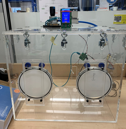
An early prototype of the Ossila Glove Box built using polymer plastic; the final version uses high quality stainless steel and glass to achieve low ingress rates that are not possible with plastics
Polymers are a popular choice for barrier materials as they are cheap, strong, and can have a wide range of material properties.
The most important thing to consider when thinking about diffusivity is the fractional free volume of the barrier material. This depends on its packing factor. In more simplistic terms, the more space there is between molecules in a barrier, the more room the gas has to diffuse through it. For this reason, permeability also depends on the size and structure of the permeant8.
Polymers consist of long chains so therefore have a low packing factor. However, whether a polymer is classed as glassy, crystalline or rubbery will affect this, and this quality depends its structure at room temperature. A glassy polymer has glass transition temperature, Tg>room temperature, RT, meaning that the polymer chains are locked into one position and the material will be characteristically brittle.9 A rubbery polymer will have Tg<RT, so is more malleable.
In glassy polymers, solubility is increased as they have an excess non-equilibrium free volume10. In other words, the polymers chains may be locked in awkward positions, leaving holes for moisture uptake. However, rubbery polymers tend have a higher free volume, as they have a more disorganized structure. Also, their polymer chains have more room to move around, facilitating diffusion through the material. For this reason, rubbery polymers tend to have higher permeability.
Crystalline materials in general have a much better packing density than rubbery/glassy poymers therefore permeants have a harder time diffusing through them. When crystalline materials form there is a point where two crystals meet called a grain boundary. There can often be atomic mismatch at this grain boundary leading to slightly larger free volume here. Thus, there may be a small ingression of moisture or oxygen at grain boundaries7.
In materials such as metal or glass, as used in the production version of the Ossila Glove Box, this amount is almost negligible.
Impact of Moisture Ingress on Glove box Atmosphere
To show how the permeability of the material results in a rise in the amount of water content inside a glove box, we have simulated how the water content inside of a glove box increases over time for different materials. We have used a wall thickness of 5mm, the values from the table above, and the moisture vapour transmission rate equation to model transfer of moisture into a box that has external dimensions of 60 x 60 x 50 cm in diameter.
For simplicity, it is assumed that this is a closed system at a constant temperature, with 0.01ppm of H2O in initially the system. We have also assumed that the change in concentration gradient across the walls (barriers) with time is negligible; by the time a non-negligible change in concentration gradient has occurred, the atmosphere in the glove box is already classed as compromised. Therefore, we have excluded the effect from this example. We have also considered separately the effect of ingress through rubber gloves using two common materials.
Log-plot of moisture levels within a sealed box, shown in parts per million by weight (ppmW) over a period of 14 days. Inset (shown on left) show linear plot of moisture levels in ppm over 12 hours.
The resulting plots show how easily the levels of moisture can build in a closed glove box environment. In a real glove box there would be additional purging of N2/Ar gas or atmosphere filtration, which would reduce the impact of this ingression. However, constantly purging an environment can quickly become expensive, and filtration media can become saturated - requiring frequent regeneration of the material. Therefore, the choice of materials when using a glove box is critical when working in an inert atmosphere.
Comparison Of Ossila Glove Box with 0.1 ppm Glovebox using Perovskite Solar Cells
In order to compare the performance of gloveboxes within a real life example, we have conducted the following experiment. Perovskite solar cells have always acheived best performances when created in an inert environment. Certain components within the materials can be very vulnerable to moisture and oxygen in the atmosphere, especially at raised temperatures. Triple cation perovskites (CsFAMAPb(IxBr1-x)3) are a particularly robust perovskite matieral but still their best devices have always been made an inert environment.
Therefore, we have made PSC devices and perovskite films (as detailed in our Ultimate guide to PSCs) in both the Ossila Glove Box and in a glovebox maintaining less than 0.1ppm O2 and H2O levels. We additionally made films in air to compare the quality of perovskite films made in and out of the glovebox entirely. It should be noted the "air" examples are made in a clean room environment in a humidity controlled lab. This will hereby represent the most control that can be held in a workable, ambient environment.
Device data of PSCs made in the Ossila Glove Box, 0.1ppm glovebox and in air.
The device performances reveal some interesting results. As expected, usable device are made in all three environments, as triple cation devices are relatively robust. However, both the average and champion PCE are almost 2% lower when devices are made in air. This clearly illustrates that in order to achieve the best performing PSC devices, higher levels of humidity control are needed than can be achieved in any ambient conditions.
Interestingly, there is no significant difference between the glovebox devices. While there is a slight decrease in the VOC for the devices made in the Ossila Glove Box, there is an improved JSC compared to those made in the 0.1ppm glovebox. The devices made in the Ossila Glove Box have a champion device efficiency of 19.2%, compared to 19.7% champion for the 0.1ppm glovebox devices. This proves that high performance perovskite solar cells can be fabricated a glovebox without having to maintain incredibly low levels of O2 and H2O - levels of >0.5% relative humidity are suitable when making PSC devices. We have confirmed this in our "Ultimate Guide to Perovskites" page, where many kinds of perovskite solar cell are made in the Ossila Glove Box.
SEM data showing films prepared in a glovebox maintaining 0.1ppm O2 and H2O levels, the Ossila Glove Box and in air. The scale bar shows 1µm.
We have also examined films prepared in these different environments with Scanning Electron Microscopy (SEM). This figure (left) shows the perovskite films made in both gloveboxes are extremely similar, showing charactirestic uniform grains seen in perovskites films. In contrast, those prepared in air have many pinholes and gaps in the film. This will clearly reduce the charge transfer properties of the perovskite layer, hindering device performance.
The SEM results correlate with the X-Ray Diffraction (XRD) and absorption data shown below, where we can see the characteristic peaks associated with the perovskite crystal structure are very strong for films deposited in both gloveboxes. This supports the argument that there is very little difference in perovskite crystal orientation when made in either GB environment.
As expected, these characteristic peaks are all strikingly reduced for the films made in air, proving the perovskite material is much less ordered.
We also show normalised absorption profiles of these three conditions. We can see that the films in both gloveboxes are almost identical, while the films deposited in air have much lower absorption in the visible region, and a tail at higher wavelength which indicates high levels of scattering seen in a rough and uneven film.
Both the film characterisation studies and the device metrics confirm there is no significant change in the quality of triple cation perovskites solar cells produced in the Ossila Glove Box and a 0.1ppm glovebox.
However, device and film performance is significantly altered when fabricated in an ambient environment, even one where humidity and cleanliness is controlled as much as possible.
We have demonstrated here in this real world example that processes requiring inert conditions can be conducted to a high standard in the Ossila Glove Box.
XRD data and absorption profiles of Triple Cation films made in the Ossila Glove Box, 0.1ppm glovebox and spin coated in air.
Glove Box
Low Running Costs
Built-In Software
Automated Purging
Available Now £7000.00
Back to Top
References
Mechanism And Optimum Shape Of Knife Edge For Metal Sealing, Y. Matsuzaki et al., Trib`ol. Int., 25 (6), 397–403 (1992); DOI: 10.1016/0301-679X(92)90077-Z.
A Review Of Glove Box Construction And Experimentation, C. J. Barton, (1961); DOI: 10.2172/4043015.
Experimental Methods And Techniques: Basic Techniques, D. A. Vicic et al., Compr. Organomet. Chem. III, 1 197–218 (2007); DOI: 10.1016/B0-08-045047-4/00008-X.
Diffusion In Solids, E. A. Irene, Electron. Mater. Sci., 81–108 (2004).
Basic Consideration Of Permeability Of Polymer Membrane To Dissolved Oxygen, H. Yasuda, J. Polym. Sci. Part A-1 Polym. Chem., 5 (11), 2952–2956 (1967); DOI: 10.1002/pol.1967.150051125.
Transport Of Dissolved Oxygen Through Silicone Rubber Membrane, S. Hwang et al., J. Macromol. Sci. Part B, 5 (1), 1–10 (1971); DOI: 10.1080/00222347108212517.
Atom Movement In Materials, D. R. Askeland, Sci. Eng. Mater., 111–137 (1996); DOI: 10.1007/978-1-4899-2895-5_5.
Correlation And Prediction Of Gas Permeability In Glassy Polymer Membrane Materials Via A Modified Free Volume Based Group Contribution Method, J. Y. Park et al., J. Memb. Sci., 125 (1), 23–39 (1997); DOI: 10.1016/S0376-7388(96)00061-0.
Glassy Polymer, J. C. Jansen, Encycl. Membr., 1 (2015); DOI: 10.1007/978-3-642-40872-4_270-1.
Comparison Of Transport Properties Of Rubbery And Glassy Polymers And The Relevance To The Upper Bound Relationship, L. M. Robeson et al., J. Memb. Sci., 476 421–431 (2015); DOI: 10.1016/j.memsci.2014.11.058.
Permeability Properties Of Plastics And Elastomers : A Guide To Packaging And Barrier Materials, L. K. Massey, (2002).
Water Vapor Permeation In Plastics, P. E. Keller et al., (January), (2017); DOI: 10.2172/1411940.
Mobility And Solubility Of Antioxidants And Oxygen In Glassy Polymers. III. Influence Of Deformation And Orientation On Oxygen Permeability, A. Boersma et al., Polymer (Guildf)., 44 (8), 2463–2471 (2003); DOI: 10.1016/S0032-3861(03)00039-9.
Physical Properties Table, R. Williamson, F. Guid. to Opt. Fabr., 102–102 (2011); DOI: 10.1117/3.892101.ch98.
Moisture Permeation Of Environmental Seals Used In Weapons, K. T. Gillen et al., (1993).
Barrier Properties Of Films, Flex. Packag. Pvt. Ltd., (2012).
Metal-Containing Thin-Film Encapsulation With Flexibility And Heat Transfer, J. H. Kwon et al., J. Inf. Disp., 16 (2), 123–128 (2015); DOI: 10.1080/15980316.2015.1046959.
Manufacturing Materials And Processing, N. R. Council., Polym. Sci. Eng. Shifting Res. Front., 66 (1994).
Flexible Organic Electronic Devices On Metal Foil Substrates For Lighting, Photovoltaic, And Other Applications, B. W. D'Andrade et al., Handb. Flex. Org. Electron., 315–341 (2015); DOI: 10.1016/B978-1-78242-035-4.00013-0.
Further Reading
An Aid to the Design of Ventilation of Radioactive areas., G. Hall et al. (2009) Nuclear Industry Guidance. Accessed at: https://www.nuclearinst.com/


Post a Comment for "Where Can I Buy O-rings for Glove Box Antechamber Door"